LINKS:
Research Paper website: https://www.uab.edu/engineering/me/images/Documents/about/early_career_technical_journal/Year_2019_Vol_18-Section3.pdf
https://github.com/Tdoe4321/VRBot
GAME PLAN
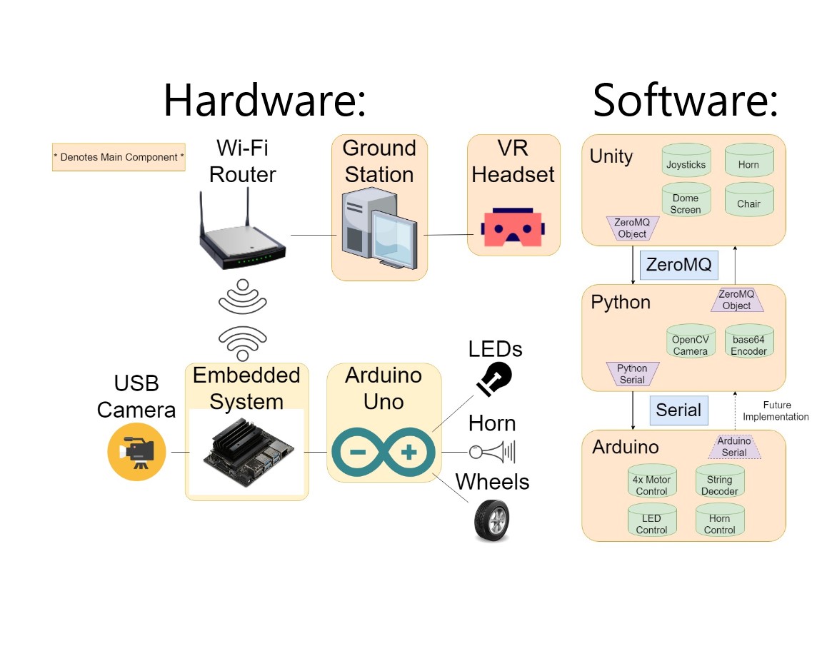
As this is an update to an earlier project, I would highly recommend checking out the first post before reading on! Like I mentioned in the overview section above, there were three main additions to the project for this update. (1) Hardware, (2) PID control, and (3) AV implementation. But, before we talk about any of that, here’s some diagrams representing the general structure of the project:
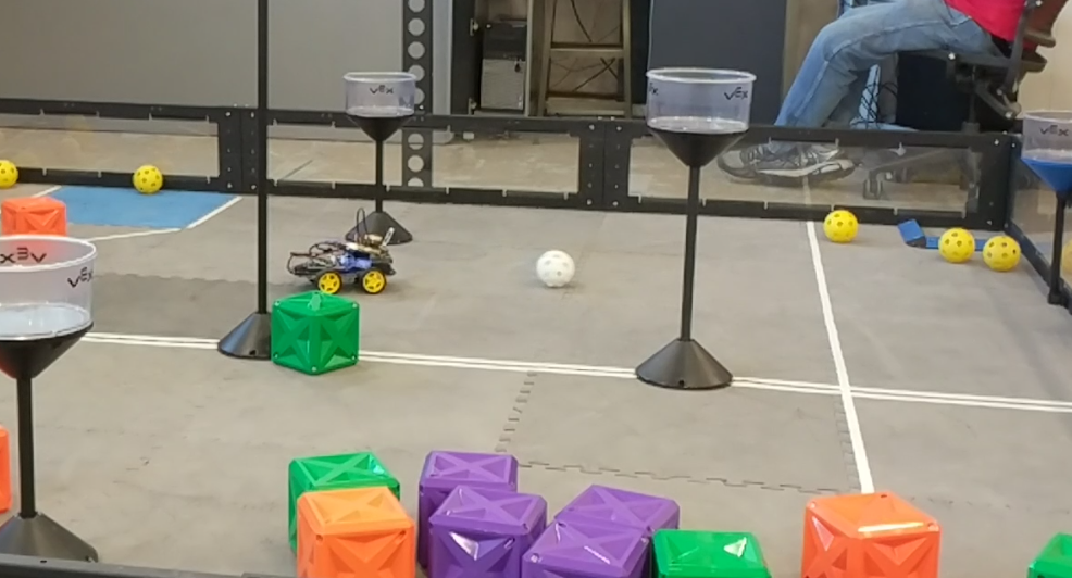
The simple way to put this, is that there are two computers (hardware) talking to each other over wi-fi thought a specific type of message (software). The first computer, the ground station, is running the VR simulation, while the second computer, the embedded system, is driving the car. This time around, I upgraded my embedded system from a Raspberry Pi to a Jetson Nano.
Hardware is probably the easiest of the three additions to explain. I added two new additions this semester, Lights and a Horn. While the lights and horn were already on-board the system before, they were not controllable in VR. They were just passive components sitting on the car. Now, however, they have UI in VR to control the! The lights are nothing special, just 4 LEDs wired in parallel to each other with a resistor in series with each LED. The 5v source comes straight from the arduino’s analog output.

Next up is the Horn. Again, nothing special about the horn either, it’s just a Piezo buzzer available super cheep from amzaon. If you’ve never seen these things before, they produce a tone at a specific frequency when you apply a square wave across them, here’s more info. I attach the buzzer across a separate output pin on the arduino to allow for control over the lights and the buzzer simultaneously.
After the hardware additions is some new software additions, namely the PID control of the car. Firstly, a quick background on PID. The aim of PID control is to try an control one variable in a system so that it ends up at whatever you input, no matter what the surrounding conditions are. For example, you may want to keep the temperature in the room 70 degrees, both in winter and in summer. Your Air Conditioning unit will have to work more or less hard depending on the outside temperature. Utilizing a PID controller, we can control how much we need to change the air, to get it back to 70 degrees.
PID stands for Proportional, Integral, and Derivative control, each contributing something to the control scheme. The proportional aspect can be thought of as the power in the system, or how snappy you want the system to respond. The Derivative acts as a damper that can take overshoot out of the system. It helps with your car oscillating about the speed you want to drive at. Finally, the integral term typically is used to control any steady-state error. This means that if you tell your car to drive at 5 m/s, but it stays constant at 4.7 m/s, the integral error can build up over time and take that out. Here’s a graphical representation:

If you want to learn more about PID control, without so much math, check out this video by MatLAB.
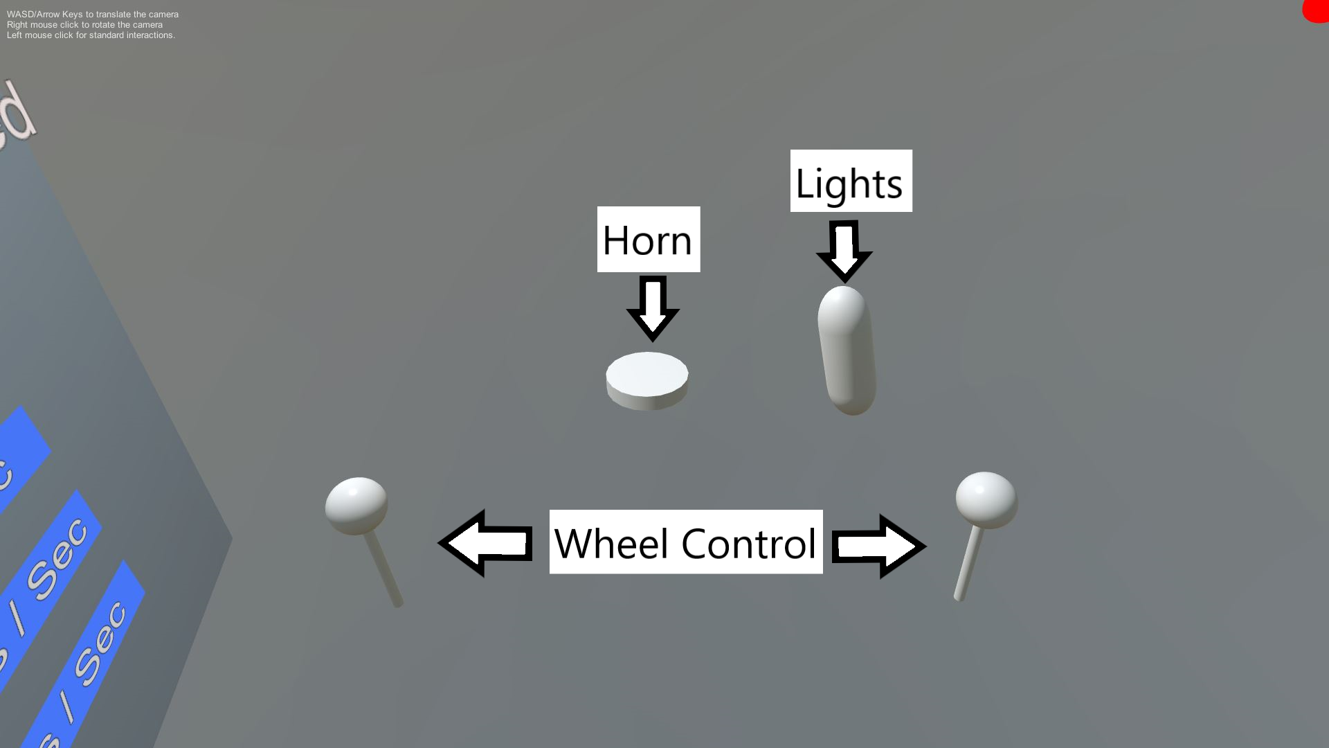
Here’s the UI for the PID control inside of VR that the user can see:

And here’s the control for the regular part of the car:
Finally, onto the last new piece added, the AR component. This was actually a relatively simple addition, in that I didn’t do much for the meantime, but there’s lots of room for easy improvement. Right now, all that I’m doing is highlighting and drawing boxes around ArUco Markers. When I identify them, they are drawn before the video gets sent over to the ground station to be displayed in VR. This means that all the video processing is happening on-board the embedded system.
It’s difficult to see the markers being drawn from pictures when you’re not actually in VR, but this is what it would look like:
